BS EN 12056 explained: the standard for drainage inside buildings
Estimated reading time 24 minutes
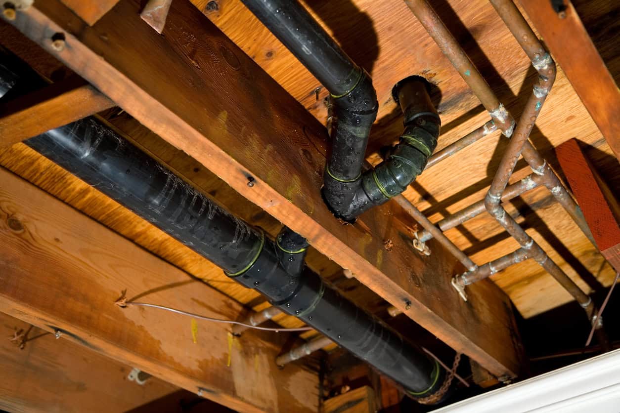
BS EN 12056 is the British and European standard for gravity drainage inside buildings. It covers everything from the trap under a washbasin to the gutter on the roof, and it stops at the point where wastewater leaves the building. Beyond that point a different standard takes over.
It comes in five parts, all published on the same day in September 2000, and not one of them has ever been revised, which is unusual for a document this widely cited and explains most of the friction around it. A standard drafted for six-litre cisterns and eight-storey buildings is still the reference for four-litre flushes and forty-storey towers, and it is still what a drainage strategy has to sit alongside.
Five parts, published in September 2000, never revised. BS EN 12056 is the oldest standard still doing routine work on a UK drainage design.
What is BS EN 12056?
BS EN 12056 is the standard titled Gravity drainage systems inside buildings. It is the UK implementation of the European standard EN 12056, published by BSI on 15 September 2000 in five parts, each covering a different element of the drainage a building holds inside its own envelope. Parts 2 and 3 carry the design content, while Parts 1, 4 and 5 carry the framework, the pumped exception and the rules for what happens on site.
- What it is. The UK implementation of EN 12056:2000, the European standard for gravity drainage systems inside dwellings, commercial, institutional and industrial buildings.
- Current edition. All five parts remain at their 2000 date. Only Part 3 has been amended.
- What it replaced. Part 2 superseded BS 5572:1994; Part 3 superseded BS 6367:1983. Both were withdrawn on the day BS EN 12056 came into effect.
- Who writes it. BSI committee B/505, Wastewater engineering, working originally through subcommittee B/505/21, Roof drainage and sanitary pipework.
- Status. Parts 2 and 3 are listed by BSI as current. Parts 1, 4 and 5 are listed as current and under review.
The British versions carry UK National Annexes, and on this standard those annexes matter more than usual. Part 2 has seven of them, NA to NG, and Part 3 has five, NA to NE. They hold the material a UK designer actually needs: the meteorological data, the ventilation rules and the test methods. All of it exists only inside the paid standard, so there is no way to read any of it short of buying a copy.
What BS EN 12056 covers, and where it stops
BS EN 12056 applies from the sanitary appliance to the point where wastewater leaves the building. Everything upstream of that point is its territory: the traps, the branch discharge pipes, the stacks, the ventilation, the gutters, the rainwater pipes, any lifting plant serving appliances below the sewer. What happens to the water after that, including where a surface water drain goes and who owns it, is a different question governed by a different document. From that point outwards, BS EN 752 takes over.
| Where the pipework sits | Governing standard | What it governs |
|---|---|---|
| Inside the building, from the appliance to the point wastewater leaves it | BS EN 12056, parts 1 to 5 | Sanitary pipework, roof drainage, lifting plants, layout and calculation |
| From that point to the treatment works or receiving water | BS EN 752, with BS EN 16933-2 for hydraulic design | System objectives, layout, management and the sizing of the network |
| Beneath a building, where the drain serves that building | BS EN 12056 and the national below-ground guidance | Treated as part of the building's own drainage system |
| Beneath a building, where the drain serves something else | BS EN 752 | Treated as an external drain or sewer |
That last pair of rows is the one worth remembering. BS EN 752 defines its own scope as beginning where wastewater leaves a building, and it picks up drains below buildings only where those drains are not part of that building's drainage system. A legacy public sewer running under a new block is BS EN 752 territory, whereas the drain from that block's own stacks is not, wherever it happens to run.
The boundary is functional, not geographical. It is not the building line that decides which standard applies, it is whose wastewater the pipe is carrying.
On a development, the external side is where the planning argument happens, because that is where a surface water drainage strategy for planning has to demonstrate rate, volume, destination and quality, and where foul drainage design for your development has to show the connection is achievable. The internal side is a building control matter, and the two run on different documents and different timescales. It is also the external side that the Lead Local Flood Authority and the other statutory consultees comment on.
The five parts, and what each one does
The five parts follow the shape of a building's drainage rather than the shape of a design process. One holds the definitions, two hold the calculations that get used, and two hold the cases that fall outside a straightforward gravity system.
- Part 1: general and performance requirements. The scope, the terminology and the performance framework the other four inherit. It carries the figure that draws the line between drainage inside a building and drainage outside it. Seventeen pages, and the shortest route to understanding what the series is for.
- Part 2: sanitary pipework, layout and calculation. The big one, at eighty-five pages. Discharge units, the flow equation, branch pipe limits, stack capacities, ventilation arrangements and the four system types. This is the part Approved Document H sends you to when a building gets too big for its own tables.
- Part 3: roof drainage, layout and calculation. Gutters, outlets, rainwater pipes and the performance requirements for siphonic systems. The only part ever amended, and the only one with UK rainfall data in it.
- Part 4: wastewater lifting plants, layout and calculation. What to do when appliances sit below the level the sewer can drain by gravity. Nineteen pages, and the part most often needed on a basement scheme.
- Part 5: installation and testing, instructions for operation, maintenance and use. Fixing, support, thermal movement, protection, accessibility and testing. The part that governs what happens on site rather than on the drawing.
Approved Document H cites Parts 1, 2 and 5 as its alternative route for sanitary pipework, Part 3 and Part 5 for rainwater, and Part 4 for pumping installations inside buildings, so all five parts are named in English statutory guidance. Most designers have never opened one.
Why the UK uses System III
BS EN 12056-2 defines four system types, and the choice between them is not a design decision. It is a matter of national tradition, written into the standard because the drafting countries could not agree on a single arrangement and settled instead on documenting all four. The UK uses System III. Approved Document H says so in a parenthesis at paragraph 1.39: "System III is traditionally in use in the UK".
| System | Full name | Degree of filling | Where it is traditional |
|---|---|---|---|
| I | Single discharge stack system with partly filled branch discharge pipes | 0.5 | Germany, Switzerland, Austria |
| II | Single discharge stack system with small bore discharge branch pipes | 0.7 | Scandinavia and the Netherlands |
| III | Single discharge stack system with full bore branch discharge pipes | 1.0 | United Kingdom |
| IV | Separate discharge stack system | Varies | France |
The practical consequence is that the numbers in BS EN 12056-2 are not universal: discharge units differ by system type, so a value lifted from the wrong column is simply wrong. Under System III a wash basin is 0.3 litres per second, a kitchen sink is 1.3 and a six-litre WC is between 1.2 and 1.7 depending on the pan. Under System I the same sink is 0.8 and the same WC is 2.0, and the resulting flow feeds straight into the pipe sizes and gradients that Part H sets out for foul water. Several UK merchant and installer sites publish the System I column as though it were the British one, which is an easy error to inherit and a hard one to spot on a drawing.
A discharge unit in BS EN 12056-2 is a flow rate in litres per second, and it changes with the system type. It is not a dimensionless fixture unit, and it is not the same number everywhere in Europe.
Scotland goes further and sets the choice out in its own guidance: its Technical Handbooks describe all four systems, confirm System III as the traditional UK arrangement, allow System II where low water consumption is the priority, and note that Systems I and IV are unlikely to suit this country. The wastewater drainage section of the handbook sets the four out in full.
How the flow is calculated
BS EN 12056-2 sizes pipework from a probability calculation rather than from the sum of what every appliance could discharge at once, on the reasoning that a building's sanitary appliances are almost never all in use together. The wastewater flow rate is the frequency factor multiplied by the square root of the sum of the discharge units connected. Continuous and pumped flows are then added on top without any reduction, because neither is intermittent.
Q(ww) = K × the square root of the sum of the discharge units. Everything else in Part 2 hangs off that one line.
The frequency factor K is where building type enters the calculation. Fifty appliances in a hotel do not behave like fifty in a stadium concourse.
- Intermittent use. K = 0.5. Dwellings, guesthouses and offices.
- Frequent use. K = 0.7. Hospitals, schools, restaurants and hotels.
- Congested use. K = 1.0. Toilets and showers open to the public.
- Special use. K = 1.2. Laboratories.
The pipe then has to carry whichever is larger, the calculated flow or the flow from the single appliance with the largest discharge unit. That second test is what stops a lightly loaded run being sized below the WC hanging off it, and it is the reason a probability method does not produce absurd results at the quiet end of a system. Our foul drainage flow-rate calculator and drainage fall calculator both show their working against the standard behind them.
Stack capacity comes from tables rather than a formula, and it turns on how the stack is ventilated and how the branches enter it. A 100 mm primary ventilated stack with swept entries takes 5.2 litres per second under BS EN 12056-2; add a 50 mm secondary ventilating stack and it takes 7.3. Approved Document H gives 7.2 litres per second for a 100 mm stack without asking how it is ventilated at all. The two documents do not give the same number for the same pipe. The reconciliation is that the Approved Document's tables are written for domestic and small non-domestic buildings only, and it says so.
Roof drainage, and the 75 mm/h that will not die
BS EN 12056-3 replaced BS 6367 in 2000 and changed how UK roof drainage is sized. The old code used a single fixed design rainfall intensity of 75 mm per hour for eaves gutters and flat roofs. The new standard replaced that with statistical rainfall data that varies by location and by return period, and is selected according to what happens if the system is exceeded.
HR Wallingford, which wrote the free design manual for the standard, put it about as plainly as a technical document can.
The fixed rainfall intensity of 75 mm/h (equivalent to 0.021 l/s per m2) recommended in the superseded BS 6367 for eaves gutters and flat roofs should no longer be used in the UK.
Manual for the design of roof drainage systems, HR Wallingford Report SR 620, 2003
Twenty-three years on, 75 mm per hour is still the figure most commonly quoted online as the British design rainfall, including on pages currently ranking for the standard itself. It is not in Approved Document H, which uses a national rainfall map instead, and the one UK document that does still state it in words is Northern Ireland's Technical Booklet N.
The real numbers vary more than most people expect. Under the Category 1 criterion used for eaves gutters, design intensity runs from about 0.022 litres per second per square metre in London and East Anglia down to about 0.010 in the north of Scotland — and the highest short-duration intensities sit in the dry south-east rather than the wet west, because a two-minute design storm is a summer thunderstorm rather than an Atlantic front.
- Category 1. A one-year return period. Eaves gutters that can overflow clear of the building, and fully watertight flat roofs that can tolerate temporary ponding.
- Category 2. A 50 per cent probability of exceedance across the design life. Valley, parapet and boundary-wall gutters where overflowing would damage the fabric.
- Category 3. A 20 per cent probability of exceedance. The same gutters where higher security is needed.
- Category 4. The maximum probable rainfall. The highest security case.
Catchment area is the other thing the standard changed. It assumes wind drives the rain at 26 degrees to the vertical, which makes the allowance simple: add half the exposed elevation area to the plan area. A six-degree pitch adds about five per cent; a 26-degree pitch adds about a quarter. The method sits behind our gutter and downpipe size calculator, and SR 620 sets it out in full.
Approved Document H's gutter table stops at 103 square metres of effective roof area and 2.16 litres per second. Past that, or on any valley or parapet gutter, the design goes to BS EN 12056-3.
Siphonic systems are the exception within the exception. BS EN 12056-3 sets their rainfall criteria and a short list of performance requirements, then deliberately stops short of a design method. That detail sits in BS 8490, reissued in February 2025 in place of the 2007 edition, so a specification still naming the older guide is naming a withdrawn document.
What was withdrawn, and what was not
Three British Standards are commonly said to have been replaced by BS EN 12056. Two of them were. The third went somewhere else entirely, and the confusion is worth clearing up, because it sends people to the wrong document and then to the wrong clause inside it.
| Withdrawn standard | Subject | Withdrawn | Replaced by |
|---|---|---|---|
| BS 5572:1994 | Code of practice for sanitary pipework | 15 September 2000 | BS EN 12056-2:2000 |
| BS 6367:1983 | Code of practice for drainage of roofs and paved areas | 15 September 2000 | BS EN 12056-3:2000, with the paved areas content going to the BS EN 752 family |
| BS 8301:1985 | Code of practice for building drainage | 1 March 2005 | The BS EN 752 series, not BS EN 12056 |
BS 6367 was in fact superseded twice: BS EN 12056-3 took the gravity roof drainage content in 2000, and BS 8490 took the siphonic content in 2007. That second handover is also the reason for the only amendment the series has ever carried. Amendment 17041, dated 30 March 2007, deleted National Annex NF from Part 3, because the test method it held had moved into BS 8490.
BS 8301 was not replaced by BS EN 12056. It went to the BS EN 752 family, five years later, because it covered drainage in the ground rather than drainage inside the building.
What actually governs a UK scheme
This is where the four nations part company, and they part company on the standard's status rather than its content. England and Wales treat BS EN 12056 as an alternative approach to their own prescriptive tables, Scotland makes it the primary route, and Northern Ireland barely uses it at all.
| Nation | Governing document | Status of BS EN 12056 | Parts cited |
|---|---|---|---|
| England | Approved Document H, 2015 edition, in force 1 October 2015 | An alternative approach to the Approved Document's own tables | 1, 2, 3, 4 and 5 |
| Wales | Approved Document H, 2002 edition incorporating the 2010 amendments | Identical wording to England, at identical paragraph numbers | 1, 2, 3, 4 and 5 |
| Scotland | Building Standards Technical Handbooks, April 2026 | The primary route. Pipework "should be constructed and installed in accordance with" it | 1, 2, 3 and 4 |
| Northern Ireland | Technical Booklet N, October 2012 | Cited only for air admittance valve conformity | 2 only |
Outside the building, the picture inverts. The Design and Construction Guidance, currently at version 2.3 of November 2023 and the document a sewer offered for adoption in England is judged against, sends the peak design flow for dwellings straight to BS EN 12056-2 System II, which is one of several reasons a scheme has to engage with the water company early. So the standard England treats as optional inside the building is the primary calculation route for adoptable sewers outside it, in a system type the UK does not otherwise use. Wales does not follow suit, and sends the same calculation to BS EN 752 instead.
The same standard is optional in an English house, mandatory in a Scottish one, and the default flow calculation for an English adoptable sewer. Which document you are judged against depends on which side of the wall the pipe is on, and which nation you are in.
There is a further gap in the English route that nobody has closed. Approved Document H says at paragraph 1.1 that its provisions apply to domestic buildings and small non-domestic buildings, and that complex systems in larger buildings should be designed in accordance with BS EN 12056. It never defines "complex". It never defines "larger". Its own tables stop at thirty dwellings, a 100 mm stack and 7.2 litres per second, and where the threshold sits between the two documents is left to engineering judgment — which is a polite way of saying it is an argument waiting to happen with a building control body. Connecting the finished system to a public sewer is a separate process again, under Section 106, and whether the receiving sewer has room for the flow is a capacity question of its own.
Drainage design queried by the council or the water company?
Tell us the site and what the drainage consultee has asked for. We come back with a fixed-fee, no-obligation quote inside 60 minutes on a working day.
Get a fixed-fee quoteWhere UK guidance still points at superseded standards
The guidance that cites BS EN 12056 is itself ageing, and in several places it points at documents that no longer exist. This is a documentation lag rather than a trap, but it costs real time for anyone who goes looking for a clause they have been told to follow and finds it was deleted eighteen years ago.
Approved Document H sends surface water designers to BS EN 752-4 and pumping stations outside buildings to BS EN 752-6. Both part numbers were withdrawn in 2008, when the seven-part BS EN 752 was consolidated into one document that was itself replaced in 2017, and the Approved Document's standards schedule still lists all seven of the 1990s parts. Scotland is closer but not current, citing BS EN 752:2008 and BS EN 1610:1998 where the live editions are 2017 and 2015. Northern Ireland's Technical Booklet N, issued in 2012, still refers designers to BS 8301 — withdrawn seven years before it was written.
Every reference to BS EN 12056 in UK statutory guidance is to the correct, current edition. Almost every neighbouring reference around it is not.
The practical answer is the one that applies to any ageing Approved Document: read the current standard and treat the intent of the guidance as the requirement. Nobody has ever been criticised for using the live version. It also helps to remember that Approved Document H is the building control test rather than the planning one, and that the two run on different evidence.
What the standard does not cover: tall buildings
The most substantial criticism of BS EN 12056-2 is not that any of it is wrong. It is that the standard was written around a building stock that no longer describes what gets built, and has never been updated to catch up.
Heriot-Watt University has run the leading UK programme on building drainage air pressure transients since the 1990s, and has been direct about the gap. A 2021 paper in Buildings recorded that design guidance extends to around thirty floors while modern towers routinely pass a hundred, and gets applied to them anyway. Its modelling found a twenty-storey single-stack system reaching a negative pressure of 70 mm water gauge, against 20 mm for a ten-storey equivalent, with trap seals stripped inside the first two seconds.
- The physical problem. Branch discharges interrupt the air moving down the stack, which generates negative transients that siphon trap seals and, at offsets and the base of the stack, positive transients that blow them out.
- The ventilation problem. Air admittance valves relieve negative pressure only. Under positive pressure they act as closed ends, and can make the transient worse.
- The evidence. A full-scale two-storey rig built to BS EN 12056 demonstrated pathogen transport between floors on airflows of 20 to 30 litres per second, the range found in real buildings, wherever a trap had emptied.
- The precedent. At Amoy Gardens in Hong Kong in 2003, dried floor-drain traps and bathroom extract fans were identified as the route by which a respiratory pathogen moved between flats. The Hong Kong Government recorded 321 cases as at 15 April 2003.
The same researchers make a point about drafting that is hard to unsee once noticed: regulations frame the water seal in a trap as odour control rather than as a barrier against pathogens. Approved Document H puts it exactly that way, saying every point of discharge should be fitted with a trap "to prevent foul air from the system entering the building". The seal is doing more work than the sentence describes, and a surcharged sewer is one of the things that empties it. A buyer, incidentally, sees none of this: a CON29DW drainage and water search reports the public network, not the pipework inside the house.
None of this makes BS EN 12056-2 unsafe for the buildings it was written for. It makes it the wrong document to hand to a designer working past twenty storeys without saying so.
The wider family of drain and sewer standards
BS EN 12056 does not stand on its own. Around it sits a set of companion standards covering the products, the pumps, the valves and the alternatives, and knowing which document holds which subject is most of the difficulty, because the subject you want is rarely in the standard you were pointed at.
| Standard | Subject | Relationship to BS EN 12056 |
|---|---|---|
| BS EN 12050 (parts 1 to 4) | Wastewater lifting plants for buildings and sites: construction and testing | The product standard for the plant BS EN 12056-4 tells you how to lay out |
| BS EN 12380 | Air admittance valves for drainage systems | The product standard for the valves BS EN 12056-2 allows as branch and stack ventilation |
| BS EN 12109 | Vacuum drainage systems inside buildings | The non-gravity alternative, outside BS EN 12056 entirely |
| BS EN 1610 | Construction and testing of drains and sewers | The outside-the-building counterpart to BS EN 12056-5, and the standard behind cover depth and bedding on a buried run |
| BS 8490 | Siphonic roof drainage systems | Supplies the design detail BS EN 12056-3 deliberately omits |
| BS EN 16933-2 | Drain and sewer systems outside buildings: hydraulic design | Where BS EN 752 sends its sizing, and the mirror of BS EN 12056-2 on the other side of the wall |
British Standards are only part of the picture on a development. Sustainable drainage design in England works to CIRIA C753 and the national standards for SuDS, along with the SuDS discharge hierarchy those standards set. Off-mains foul drainage runs to BS 6297 and the general binding rules, soakaway design to BRE Digest 365, and water reuse to BS EN 16941 and BS 8515, which is where rainwater harvesting sits. Our free drainage calculators show the working against the standard behind each one, and the flood risk and drainage glossary unpacks the terminology.
How to get a copy of BS EN 12056
BS EN 12056 is a paid standard, sold by BSI through BSI Knowledge and BSOL. There is no free, lawful full-text version of any part of it, and the copies circulating on document-sharing sites are unauthorised reproductions of BSI copyright material.
- What to buy. Parts 2 and 3 carry the design content and cost roughly twice what the other three do; the full set of five runs to a little over a thousand pounds at list price.
- What is lawfully free. BSI publishes the national foreword of every part on its product pages, which is where the supersession and amendment history sits.
- The best free companion. HR Wallingford's design manual for Part 3, Report SR 620, is a complete and citable guide to the roof drainage method and its National Annexes.
- How to check before buying. The NBS publication index confirms which edition and which amendments are current, at no cost.
Universities, larger consultancies and some public libraries hold BSOL subscriptions covering the whole series, so it is worth asking before buying. If the question is a roof drainage one, SR 620 will answer most of it for nothing.
Standards say what a system has to achieve. Turning that into a scheme a council, a water company or a building control body will accept is a separate exercise, and it is where most of the argument happens. If you need foul drainage design for your development, a surface water scheme prepared and defended through planning, or simply a straight answer on which document your site is being judged against, our drainage strategies for planning cover it, including discharging drainage planning conditions and the process and cost of getting them signed off. Call +44 (0) 1293 214444 or email enquiries@unda.co.uk and one of our experienced consultants will come back to you the same working day.
Frequently asked questions
Is BS EN 12056 mandatory in the UK?
It depends where you are building. In England and Wales it is voluntary: Approved Document H offers it as one accepted route to compliance alongside its own tables, so a design can satisfy Part H without ever opening it. In Scotland the Technical Handbooks say sanitary pipework "should be constructed and installed in accordance with" BS EN 12056-2, which makes it the expected route rather than an option. A contract or a water company's adoption requirements can also make it binding anywhere.
Which part of BS EN 12056 do I actually need to buy?
Almost always Part 2 or Part 3, and rarely both. Part 2 is the one for sanitary pipework, stack sizing and ventilation; Part 3 is the one for gutters, rainwater pipes and siphonic performance. Part 1 is short and mostly definitions, Part 4 only matters if something is being pumped, and Part 5 covers installation and testing. If the question is a roof drainage question, read HR Wallingford's free manual first and you may find you do not need to buy anything.
Is BS 5572 still valid?
No. BS 5572:1994, the code of practice for sanitary pipework, was withdrawn on 15 September 2000, the day BS EN 12056-2 came into effect. Copies still circulate and older specifications still name it, so a design worked up from BS 5572 will be using superseded guidance — something that tends to get picked up on review rather than on site.
Who checks compliance with BS EN 12056, building control or the planning authority?
Building control. BS EN 12056 sits behind the Building Regulations, so the pipework inside the building is checked by a building control body against Part H, or against the Scottish or Northern Irish equivalents. A planning authority and its drainage consultee are looking at a different question entirely, which is what leaves the site and where it goes. The two processes do not talk to each other, and a scheme can satisfy one while failing the other.
Does BS EN 12056 cover rainwater harvesting or greywater reuse?
No. It covers the gravity drainage that carries rainwater and wastewater away, not any system that stores or treats it for reuse. Rainwater harvesting is covered by BS EN 16941-1 and BS 8515, and greywater reuse by BS EN 16941-2 and BS 8525. Where a harvesting system is fitted, BS EN 12056-3 still governs the gutters and pipes feeding it, and the overflow still has to be designed for the full design storm. Our rainwater harvesting calculator sizes the storage side.
What does "degree of filling" mean, and why does it differ between systems?
It is the proportion of the pipe's cross-section the standard assumes is running with water. System III, the UK arrangement, assumes a branch discharge pipe runs full, so its degree of filling is 1.0. System I assumes half full, at 0.5, and System II assumes 0.7. The figure is not a design choice; it is the assumption baked into that system's discharge units and pipe tables, and it is why the values from one system cannot be used in another.
About the author. Edward is a co-founder and Director of Unda with 20+ years in flood risk and drainage, and a national-press commentator on flooding. Unda has been trading since 2014, is a CIWEM Business Partner with CIWEM member and chartered (C.WEM MCIWEM) consultants, and has delivered 5,000+ flood risk assessments and drainage strategies across England and Wales.
Edward Bouët · BSc (Hons)
Latest news




One of our experienced Flood Risk Consultants will get back to you within 60 minutes
