A silt trap, a reed bed and a strip of scrub: Sri Lanka’s 2,000-year-old tank cascade system
Estimated reading time 20 minutes
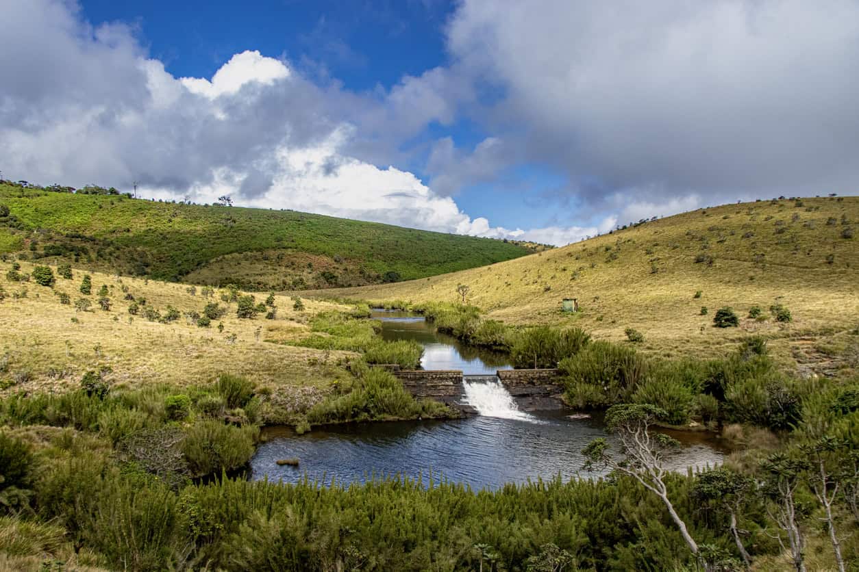
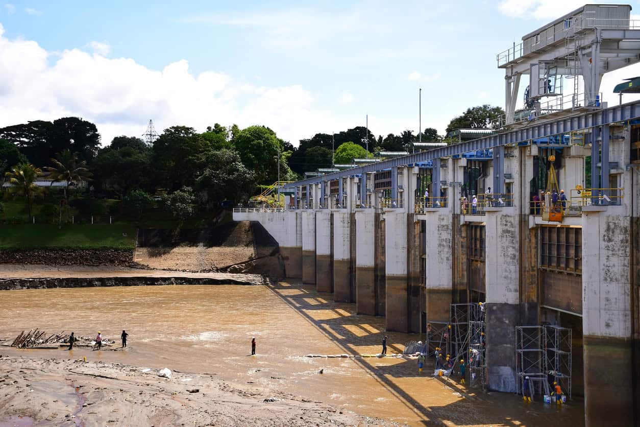
A tank cascade system is a chain of small reservoirs built down a shallow valley in Sri Lanka's dry zone, so that the spill and seepage from each one becomes the inflow to the next. Thousands of them survive, and the earliest were dug before the Romans reached Britain. What should interest a UK drainage engineer is not the storage, though. It is that a village tank was never only a pond. It came with a silt trap upstream, a tree belt around the water, a filtering meadow on the inflow, and a strip of scrub and marsh below the bund that took salts and dissolved iron out of the seepage before it reached the paddy.
Quantity, quality, amenity and biodiversity, arranged in series, about two thousand years before anyone in Britain wrote them down as SuDS design objectives.
A field assessment of one Sri Lankan cascade found most of its micro-land uses degraded, and the worst of it concentrated downstream and in the valley bottoms. That is exactly where the water-quality components sit.
What is a tank cascade system?
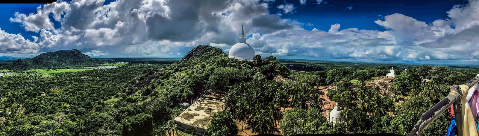
A tank cascade system is a connected series of small reservoirs, or tanks, laid out down a micro-catchment so that water released or seeping from an upper tank is caught by the one below it. Very little leaves the valley uncaptured. The Sinhala term is ellaṅgāva, usually glossed as a set of things hanging one next to another, which describes the arrangement about as well as anything in English does.
FAO designated the arrangement a Globally Important Agricultural Heritage System in 2017, under the name "The Cascaded Tank-Village System in the Dry Zone of Sri Lanka". Locally it is Ellanga Wev Gammana.
The numbers are contested, and worth stating honestly rather than tidily. Bebermeier and colleagues put the bulk of construction in the Anuradhapura kingdom, between roughly 377 BCE and 1017 CE, with the peak between 200 and 950 CE, and count about 10,000 village tanks still in use today. Estimates of the total surviving stock disagree: Panabokke's figure of around 18,000 and Dharmasena's of more than 30,000 are competing counts of the same thing, not a modern remnant and an ancient total. FAO's own nomination document identifies roughly 14,200 operational irrigation tanks.
One cascade, Mahakanumulla in Anuradhapura District, carries 28 village tanks and 12 villages across about 4,450 hectares, and 3,432 people live in it. It is the cascade most of the recent field research has been done on.
We drew the cascade to see what the published figures leave out. The meso-catchment draining to the outlet measures 39.6 km², and runs 10.1 km from the catchment head to the point where it empties into Nachchaduwa Reservoir. The published assessment counts 28 village tanks; the cascade map numbers 29. Two figures off our own drawing are worth pulling out. A third of the catchment, 1,360 hectares, is valley bottom sitting less than two metres above the nearest channel. And 19.2 km², close to half of it, drains through a single tank, Mahakanumulla wewa, before reaching anything else.
That second figure is what people mean when they call a cascade a system rather than a collection. Half the catchment passes through one tank. Whatever that tank does to the water, it does to half the water.
Nothing exotic went into that drawing. The tank outlines come from OpenStreetMap where the tank is mapped there; the catchment boundary, the micro-catchment divides and the valley bottom are ours, derived from SRTM terrain tiles by depression-filled flow routing. It is the same GIS and terrain-model work that sits behind a UK catchment plan, run on a catchment in Anuradhapura District instead of a Surrey one.
Seven components, seven jobs
What makes a village tank different from a reservoir is that it arrives with a set of associated land uses, each doing one job, arranged in order down the catchment. Take any of them away and the tank still holds water. It just stops doing something else. Anyone who has put together a surface water drainage strategy that treats water quality as a design requirement will recognise the logic, if not the vocabulary.
The definitions below follow FAO's nomination document and the ecological survey by Geekiyanage and Pushpakumara. The right-hand column is ours, and it is a rough mapping rather than an equivalence.
| Component | What it does | Nearest modern counterpart |
|---|---|---|
| Upstream soil ridge (iswetiya) | Stops soil eroded off the slope above from reaching the tank at all. | Cut-off ditch or interceptor bund |
| Silt trap and animal pond (godawala) | Settles sediment out of the inflow, and keeps cattle out of the storage. | Sediment forebay |
| Tree belt (gasgommana) | Wind barrier. Cuts evaporation off the water surface and wave run-up on the bund. | Shelter planting and bank protection |
| Filter meadow (perahana) | Sedges and grasses strain the remaining sediment out of the inflow. | Filter strip or reed bed |
| The tank | Holds the water and releases it under control. | Attenuation basin or pond |
| Outlet chamber (bisokotuwa) | Carries the gate, and drops the pressure so the outlet barrel discharges at controlled velocity. | Flow control chamber |
| Seepage interceptor (kattakaduwa) | Catches seepage below the bund and strips salts and dissolved iron out before the water reaches the paddy. | Bioretention strip or treatment wetland |
Between them these components cover the ground UK practice now calls the four pillars of SuDS: water quantity, water quality, amenity and biodiversity. The cascade did not treat those four as objectives to be balanced against one another. It treated them as separate pieces of hardware, each with a job, arranged in the order the water met them. The silt trap is the direct ancestor of the field-edge sediment pond; the tree belt and the seepage strip are what nature-based drainage is reaching for.
A component that exists on the layout only as green shading is a component that has not been given a job.
The outlet that does two jobs
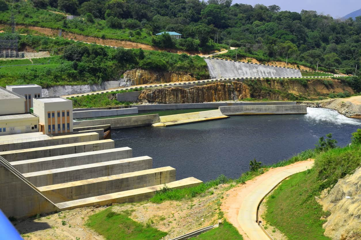
The outlet at the base of a Sri Lankan tank is called a bisokotuwa. It is an enclosure built across the culvert on the upstream face of the bund, and the standard engineering description is precise about it.
- Position. Across the culvert on the upstream face of the bund, with the longer side of the rectangle parallel to the bund.
- Construction. Thick brickwork laid in mortar, backed with a watertight skin of tempered puddle clay, and lined inside with closely fitted stone slabs laid horizontally on edge.
- Size. Typically 8 to 12 feet long and 8 to 10 feet wide.
- Job one. It held the gate and the gear that worked it.
- Job two. It dissipates energy, which is the part nobody quantified until this century.
The second job is hydraulic. The chamber is far larger in section than the barrel leaving it, so water entering it slows, generates steep velocity gradients and shear, and loses pressure. The barrel then discharges at a controlled velocity instead of at full reservoir head. A 1:30 scale physical model reported in the Ceylon Journal of Science in 2023 measured the loss at about 43.5% of the inflow's kinetic energy, and found it held steady regardless of the head behind it.
That measurement was published in 2023. The structure it describes is roughly seventeen centuries old.
There is a story in circulation that Victorian engineers misread the chamber as a European valve pit and fitted gates to structures that never had them, with Henry Parker's Ancient Ceylon (1909) named as the source of the error. Parker's own text does not support it. He argued from physical evidence, including square sockets cut into the floor at Minneriya to take the tenons of vertical posts and twin reduced-area outlets at Pavat-kulam, that the ancient chamber held wooden valves and lifting gear, and he said plainly that since no woodwork survives the detail could only be conjectured. He was not projecting a modern fitting backwards. He was giving the Sinhalese the priority:
Since about the middle of last century, open wells, called "valve-towers" when they stand clear of the embankment and "valve-pits" when they are in it, have been built at numerous reservoirs in Europe. Their duty is to hold the valves, and the lifting-gear for working them, by means of which the outward flow of the water is regulated or totally stopped. Such also was the function of the bisokotuwa of the Sinhalese engineers; they were the first inventors of the valve-pit, more than 2100 years ago.
Henry Parker · Ancient Ceylon (1909), p. 379
What Parker had no way of knowing was how much work the chamber was doing on its own. Nobody measured that for another hundred and fourteen years.
A canal that works as a reservoir
The cascades scale up. The Yodha Ela, or Jaya Ganga, is a canal built under Dhātusena in the fifth century AD, running about 87 km from Kala Wewa to Tissa Wewa at Anuradhapura. The gradient is commonly cited as around 10 cm per kilometre, near enough 1 in 10,000, though that figure is a widely repeated one rather than a measured one and should be treated as such.
The design detail that matters is that it was banked on one side only. Water spread laterally off the unbanked side into the tanks and paddy along its length, so the canal did not simply convey water from one end to the other. It worked as a long, moving reservoir, feeding the system it passed through. Conveyance and storage were the same asset, which is not a trick Roman drainage engineering attempted.
The policy behind the programme is on the record. The Cūḷavaṁsa puts it in the mouth of Parākramabāhu I: "not even a little water that comes from the rain must flow into the ocean without being made useful to man." It is chronicle testimony written up after the fact, in the panegyric register the chronicle uses for that king throughout. But it is a documented statement of intent rather than a folk saying, and it describes what the works actually do.
Which parts are failing, and which parts are not
Ratnayake and colleagues assessed 430 land-use units across the Mahakanumulla tank cascade system in 2022, combining participatory scoring with 60 community members, expert workshops and field verification. Their finding, stated plainly in the paper: "the majority of micro-land uses were degraded."
Where the degradation sits is the part worth reading twice. Hotspots concentrate downstream and in the valley bottoms of the meso-catchment. The biodiversity bright spots are midstream. The downstream land-use systems were, in the authors' words, "found to be more vulnerable to degradation and insufficient to provide" ecosystem services.
Be precise about what that does and does not show. It is a spatial result, not a functional one. The paper did not set out to compare storage components against water-quality components, and it did not run that test. What it establishes is that the downstream end of the cascade is where condition is worst, and the downstream end is where the seepage interceptor sits.
Alongside that sits a longer-standing criticism of how the tanks have been rehabilitated. A 2013 review for Sri Lanka's Hector Kobbekaduwa Agrarian Research and Training Institute put it this way:
limiting the development interventions to hardware aspects such as repair of tank structures and development of community infrastructure; developing individual tanks without paying attention to cascade connections; and insufficient attention paid to restoration of tank bed and its surrounding eco-system.
M. M. M. Aheeyar · HARTI Research Report 162 (2013), citing Dharmasena (2007)
A 2021 paper by the same group that produced the Mahakanumulla assessment goes slightly further, finding that restoration carried out without analysing how the cascade actually functions "has caused unintended degradation to cascade anatomy during various VTCS rehabilitation projects."
Unintended is the operative word and it should stay in. Nobody set out to remove the water-quality components. FAO's nomination records that some recently renovated tanks do keep provision for restoring the tree belt, the silt trap and the drainage way. This is neglect and inattention under real constraints, not vandalism, and it is the same pattern the evidence base for nature-based measures keeps running into: the components hardest to inspect are the ones hardest to defend.
Why this keeps happening here as well as there
Since 17 August 2026, NPPF Policy F8 has required drainage on development of any size to be designed to the 2025 National Standards for Sustainable Drainage Systems, with a SuDS statement submitted under Annex C. Water quality is one of the seven standards. That is a real change, and we have set out what it requires in detail.
What the standards still do not do is name a single body responsible for maintaining what gets built. That gap is the mechanism by which the same thing happens in Surrey that has happened in Anuradhapura, whatever the discharge hierarchy says on the drawing.
The reason is a difference in how the two halves of a drainage system fail. A quantity component fails loudly. An outfall silts up, a basin surcharges, a car park floods, somebody rings the council: surface water flooding is nothing if not visible. A quality component fails silently. A filter strip mown to lawn, a swale levelled by a groundsman, a forebay nobody has desilted since handover: none of these flood anything. They stop treating water, and no part of the inspection regime is looking. The one moment the water quality case does get read closely is at application stage, which is why it is such a common thread in the reasons a drainage strategy gets objected to.
The half of a scheme that gets inspected is the half that fails visibly. That is not the same as the half that matters.
CIRIA's C821 guidance is England's most serious recent attempt at the other model: it sets out what community groups can lawfully maintain, and what they cannot. It is worth reading next to a cascade, because a cascade was maintained by the households that drank from it.
What the cascades had that a UK scheme usually does not
Two things, and neither is mysterious: the people who maintained the system were the people who used the water, and taking out any one component visibly degraded the next one down.
Take the first. The interceptor strip below the bund was not somebody else's asset in an adoption dispute. If it silted up, the paddy salinised, and the household farming the paddy knew why.
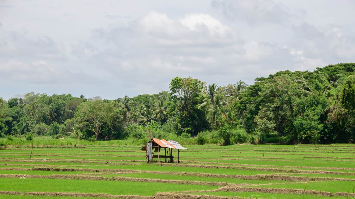
The second is legibility, and a tank cascade system has it to an unusual degree. Take out the silt trap and the tank fills with sediment. Take out the interceptor and the paddy goes saline. The consequence arrives at the person who caused it, quickly enough to connect the two. A modern scheme is rarely built that way, which is why source control at plot level and a real, component-by-component maintenance plan do more work than a schedule written to discharge a drainage condition and then filed.
Set against that, the honest limit: the cascades are degrading too, on the published evidence, and they are doing it under pressures no design solves. Encroachment, changed cropping, depopulation. So this is not a story about ancient superiority. It is a story about what happens to the parts of any water system that nobody is obliged to look after, told over a longer run than the UK has data for.
Nobody is about to propose a tank cascade system in West Sussex. The transferable part is the discipline: name every component, give each one a job, and say who keeps it working. If you are working up a drainage strategy for your planning application and the water quality case is the part still to be written, that is the half worth getting right first. Ground conditions decide how much of it you can do by infiltration, so BRE 365 testing and the free drainage calculators are where the numbers start. It is the half that will still be doing its job in ten years, or will quietly have stopped, depending on what the surface water scheme was asked to prove.
Frequently asked questions
Are Sri Lanka's tank cascades still being restored?
Yes. The World Bank's Climate Smart Irrigated Agriculture Project and related programmes work across village cascades in the dry zone, and the emphasis has shifted from renovating single tanks to planning at cascade level through community-based Cascade Management Committees. The World Bank's own 2023 assessment argues that ecosystem services should become part of how rehabilitation is judged, which is a fair summary of what the research has been saying.
Is a tank cascade the same as a chain of attenuation ponds?
No, and the difference is the point. A chain of attenuation ponds is a quantity solution: several storage volumes in series, sized to control a discharge rate. A tank cascade puts a differentiated set of components in series, each doing a different job: sediment capture, filtration, evaporation control, storage, seepage treatment. The storage is one element of a cascade, not the whole of it. If you are working out whether a scheme needs a flood risk assessment, a drainage strategy or both, that distinction between rate and treatment is the one that matters.
Do UK drainage schemes have to treat water quality, or just manage flow?
Both. Water quality is one of the seven 2025 National Standards, so a drainage strategy that only demonstrates rate and volume is incomplete. In practice that means showing how the first few millimetres of runoff are intercepted and treated at source, and scoring the proposed features against the site's pollution hazard. Most councils want that summarised on a SuDS proforma alongside the strategy. Habitat value is assessed separately again, and whether SuDS count towards biodiversity net gain is its own question.
Who looks after a SuDS scheme once the development is finished?
It depends on what was agreed, and that is the honest answer rather than a dodge. Schedule 3 of the Flood and Water Management Act 2010 remains uncommenced in England, so there is no statutory SuDS approving body and no single named adopting authority. Responsibility falls to whatever the planning condition, the section 104 agreement or the management company arrangement says it does. Our guide to the 2025 National Standards sets out where the regime has got to and where it has not.
About the author. Edward is a co-founder and Director of Unda with 20+ years in flood risk and drainage, and a national-press commentator on flooding. Unda has been trading since 2014, is a CIWEM Business Partner with CIWEM member and chartered (C.WEM MCIWEM) consultants, and has delivered 5,000+ flood risk assessments and drainage strategies across England and Wales.
Edward Bouët · BSc (Hons)

One of our experienced Flood Risk Consultants will get back to you within 60 minutes
