129 drains and half a metre of loam: how Machu Picchu handles two metres of rain a year
Estimated reading time 19 minutes
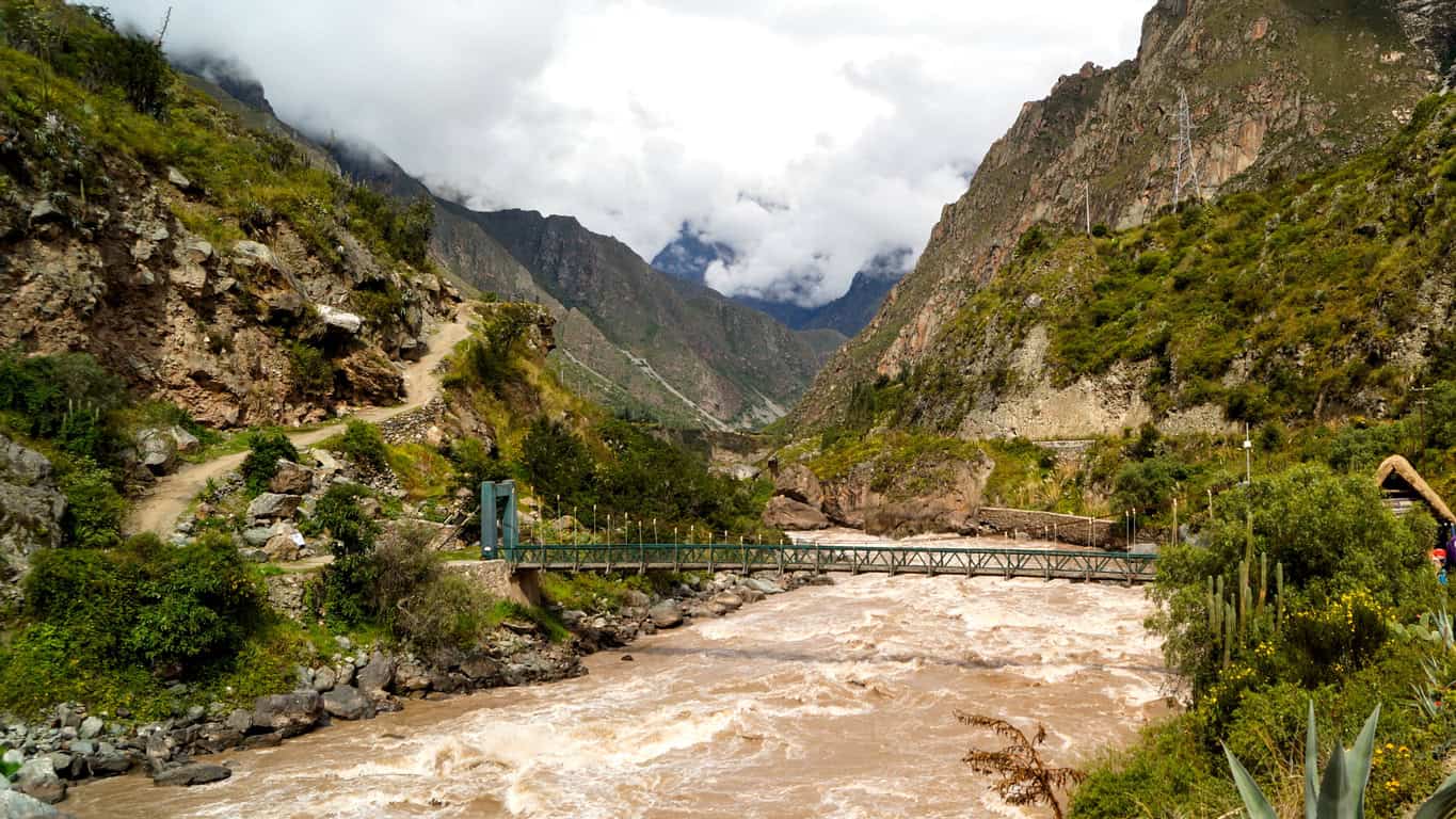
Machu Picchu takes close to two metres of rain a year on a granite ridge that falls away at roughly 50% either side, and it has stood there for around six centuries. The photograph everybody knows is the part above ground. The Machu Picchu drainage system that keeps it there is almost entirely invisible: 129 outlets built into the walls as they went up, a main drain routed along a geological fault, and terraces that are not agricultural platforms at all but retaining structures with a graded filter inside them. The engineer who surveyed the site, Kenneth Wright, reckoned something like 60% of the construction effort went below ground.
This is the sixth article in our drainage history series, after Roman drainage and flood management and what a medieval disaster teaches us about back-to-back flooding. It is also the most technical, because the numbers survive.
On the agricultural terraces, Wright estimated that about 90% of the annual rainfall infiltrated and only 10% ran off. An engineered surface, on a steep slope, in 1,940 mm of rain a year.
The design condition: two metres of rain on a granite ridge
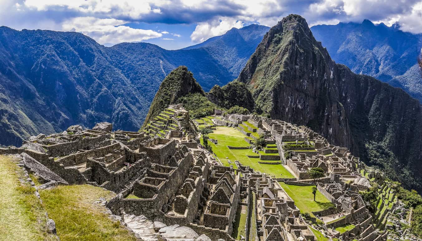
The site was wet, steep and unstable before anything was built on it. Ice-core reconstruction puts annual precipitation during the occupation, roughly 1450 to 1540, at about 1,940 mm a year, against a long-term average nearer 1,990 mm. The wettest parts of Cumbria manage around 3,000 mm; most of lowland England sits between 600 and 800 mm on the Met Office climate averages. Machu Picchu is not extreme by global standards. It is simply very wet, on a very steep slope, with almost no natural soil.
The rock is granite, heavily fractured. Rualdo Menegat's 2019 work for the Geological Society of America mapped a network of faults intersecting beneath the site in an X pattern, including one running some 170 km, and argued that the fracturing is why the Inca chose the spot: it produced building stone that broke cleanly along planes of weakness, and it drained.
The ridge they picked is a saddle between two peaks with a spring on its north slope, feeding a canal 749 m long at about 3% gradient into a cascade of 16 fountains. Everything after that was construction. Wright's team recorded at least one landslide during the build, still visible as a one to two metre offset in the terrace alignment near the main drain, which suggests the Inca were working the problem as they went rather than executing a finished design. The same order of decisions sits behind a surface water drainage strategy built around infiltration on an English site today: establish what the ground will accept, then let the layout follow.
What 1,940 mm a year looks like on the ground
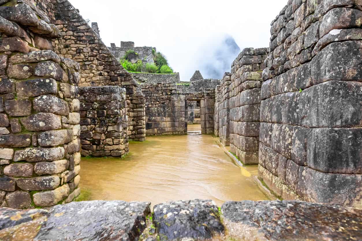
Nearly all of that rainfall arrives between October and April. The design problem was never the annual total. It was the intensity of a wet-season storm landing on bare rock and thin soil, on a slope steep enough to move it, and the need to get that water off the built area and into the ground before it did any work on the walls.
129 outlets, designed per unit area
Wright's 1999 survey for the American Society of Civil Engineers counted 129 drain outlets set into the stone retaining and building walls of the urban sector. The significant figure is not the count but the density: roughly one outlet per 200 m² of tributary area. That is a provision rate applied across a site, not a set of holes punched wherever water happened to collect.
- Count. 129 outlets, counted on site, set into the retaining and building walls.
- Size. Typically 10 × 13 cm.
- Density. About one outlet per 200 m² of tributary area.
- Design flow. Around 500 L/min each, with a maximum of about 650 L/min.
- Timing. Built into the walls at initial construction, not cut in afterwards.
- Interception. A separate interceptor drain about 42 m long runs north to south through the agricultural terraces, catching surface water before it reaches the built area.
The timing is what matters. These were not weep holes added when a wall started to weep. They were part of the wall from the first course, which means a tributary area had been worked out, a flow assumed and a provision rate set before the stone went down. Back-calculating from outlet size and spacing, Wright arrived at an implied design storm of the order of 200 mm/hr at a runoff coefficient of 0.8, a figure that says more about the margin built in than about any storm anyone measured.
The main drain follows a fault
The boundary between the agricultural and urban sectors is itself a drain, and it sits on a line of geological weakness. Wright's survey found that the main drain, the "dry moat" carrying water off the site and into the forest below, overlies a local fault. Whether the Inca deliberately selected the fault as a route, or whether the fault simply produced the topographic low that water was always going to follow, is not settled by the evidence. The defensible description is that the drain follows the fault.
The fissures below the site likely allowed it to drain, one of the reasons the city has lasted so long.
Rualdo Menegat · Geological Society of America annual meeting, 2019
Either way, the geology decided where the water went, and the English version of that is duller and just as decisive. Whether a site can discharge to ground is a question about what is underneath it, answered by the geology beneath the site first and a trial pit second. Chalk or river terrace gravel will usually infiltrate. London Clay, or glacial till described optimistically as "clay, sand and gravel", usually will not, and design intent does not change it. Where the ground is marginal, groundwater monitoring often decides the question before any soakaway is designed.
The terraces are not planting beds
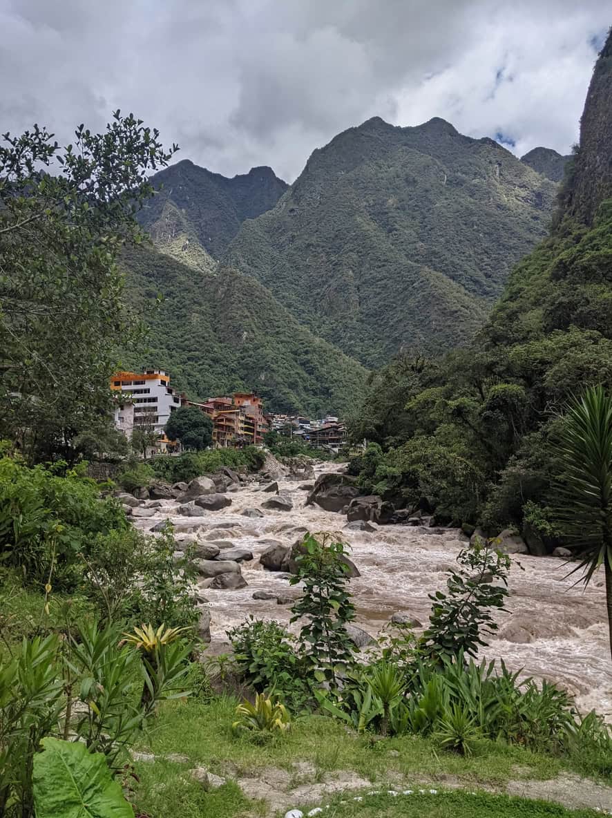
This is the part that gets photographed and misread. The terraces look like farmland stacked on a hillside. Structurally they are retaining walls with graded granular fill behind and beneath them, and the growing medium is the last half-metre of a drainage system. Wright described the build-up from the base as ungraded rock chips and stones, the waste from stone-cutting reused as free-draining fill, then gravel, then a somewhat sandy layer, then topsoil typically 0.5 m thick. Beneath the plazas the chipped-rock layer is around 1 m thick.
That sequence is a filter. Each layer is finer than the one below it, so water moves down through progressively coarser material while the fines above are held in place rather than washed into the voids beneath. The ASCE, which lists the site as a historic civil engineering landmark, describes it as "subsurface drainage using inverse filters". British practice calls the same arrangement a graded filter, and it is what stops a granular drainage layer silting up — the job a geotextile or a filter drain does today. The Inca had no filter criteria to work to. They had the observation that fine material placed straight onto coarse material on a wet slope eventually fails.
| Layer | Material and thickness | Function | Modern equivalent |
|---|---|---|---|
| 4 (top) | Sandy loam topsoil, typically 0.5 m | Growing medium; infiltration approx. 10 cm/h | Topsoil over a SuDS surface |
| 3 | Somewhat sandy material | Transition; retains the fines above | Filter sand, or a geotextile separator |
| 2 | Gravel | Filter step; coarsens downwards | Graded granular filter |
| 1 (base) | Ungraded rock chips and stones; approx. 1 m under the plazas | Storage and conveyance; approx. 160 m/day | Clean stone storage layer |
| Through the wall | Outlet, 10 × 13 cm | Positive discharge; one per 200 m² | Weep hole or outfall to a filter drain |
Two independent studies have since examined the same ground with instruments Wright did not have. A 2023 survey in Scientific Reports, using ground-penetrating radar, resistivity and magnetometry, resolved distinct layers at 80 cm, 94 cm, 1.49 m and 2.40 m and described an overlapping of stratigraphic levels of differing granulometry that it read as deliberately intended to increase permeability. A 2025 paper in Built Heritage, using dynamic penetrometer testing at fifteen points inside the site, defined what its author calls Inca Controlled Fill, graded clasts in layers of decreasing particle size, and measured its average thickness at 1.10 m under the agricultural platforms and 1.50 m under the squares, with about 0.50 m of organic soil above.
That 0.50 m is Wright's half-metre of topsoil, measured again three decades later by a different team using a different method.
Nine tenths of the rain went into the ground
Wright's water balance, restated in his 2021 review in Water, is the most immediately useful part of the survey for a British engineer, because it is expressed in the units a modern infiltration test reports. Four figures carry it.
- On the agricultural terraces, about 90% of annual precipitation infiltrated and about 10% ran off.
- In the urban sector, paved and roofed, roughly 60% ran off and 40% infiltrated.
- Topsoil infiltration was around 10 cm/h, or 100 mm/hr, about 2.8 × 10⁻⁵ m/s.
- The plaza chipped-rock layer, at around 160 m/day, is about 1.9 × 10⁻³ m/s.
Those sit squarely inside the range a BRE Digest 365 soakage test reports on an English site. A design infiltration rate of 1 × 10⁻⁵ m/s is a good result across most of southern England; 1 × 10⁻³ m/s is river terrace gravel. The Inca were not achieving permeability that a sand and gravel site does not achieve naturally. They were building that performance into a surface constructed from nothing, on a slope where no such soil existed. If you have trial pit timings of your own, you can calculate an infiltration rate from your own BRE 365 test data and see where a site lands against those numbers.
The split between the two sectors is the whole modern argument in miniature. The same rain fell on both. The terraces, engineered to infiltrate, shed a tenth of it. The urban sector, paved and roofed, shed six tenths. Cover a permeable surface and runoff rises by a factor of six. That is why permeable paving is worth arguing for on a hardstanding, and why a capped surface produces infiltration-excess overland flow in a downpour. An English drainage strategy has to show what happens to that difference, usually as attenuation storage.
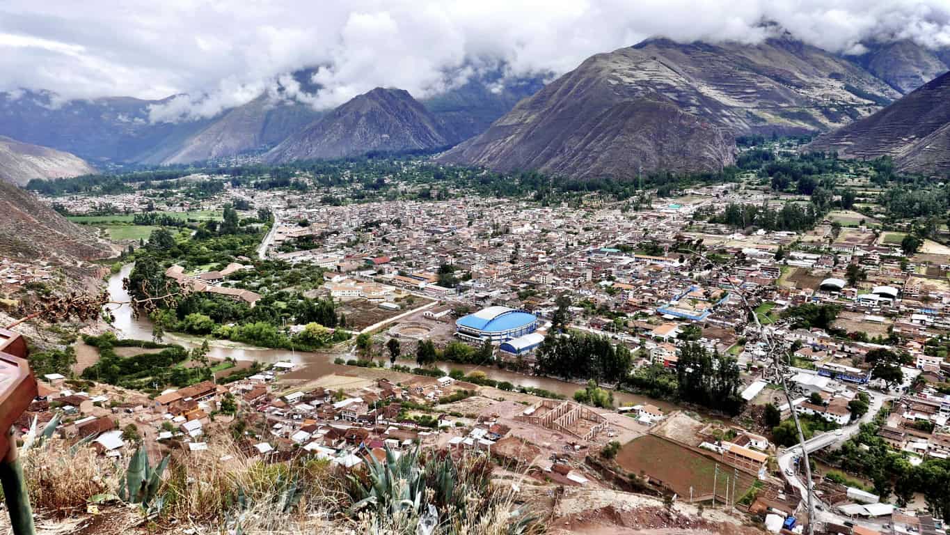
The same rain, a different surface
A terraced slope took nine tenths of the rainfall into the ground. A roofed and paved surface sheds most of it, and sheds it quickly. That is the whole of the modern surface water problem in one comparison, and it is why a drainage strategy is judged on what it does with the difference between the two.
So why has it not slid down the mountain?
The obvious question about a six-century-old settlement on a 50% slope is whether it is moving, and for a while the published answer was that it was. In 2001 a team from Kyoto University reported ground movement beneath the site of about 1 cm a month, presented as a landslide precursor. The figure travelled a long way. It was wrong.
Two independent instrumented programmes measured it. A 2007 study in Geomorphology recorded dilatometric movement of 0.5 to 3.5 mm over two and a half to nearly four years, and concluded that fast deep-seated slope movement was not confirmed by its monitoring. An Italian programme using GPS, laser scanning and satellite radar interferometry independently found maximum displacements of about 9 to 12 mm a year, with the upper part of the citadel showing no measurable movement at all.
The claimed rate was roughly 12 cm a year. Two independent programmes, using different methods, measured about 1 cm a year, localised, with the built area stable.
So the ridge creeps, slowly, as steep ground does. What it is not doing is failing. Water that infiltrates through a graded filter and leaves through a designed outlet does not build pore pressure behind a retaining wall; water that ponds behind an unfiltered wall does. The stonework, the batter on the walls and the trapezoidal doorways are all secondary to that.
What is measured, what is estimated, and what nobody has checked
Wright's survey is careful about its own limits; the retellings of it are not. Three things need stating plainly before anyone repeats the headline figure again: his team were never allowed to excavate the terraces, the 60% is an estimate of labour rather than a measurement of fabric, and in twenty-seven years nobody has independently tested it. None of that makes the engineering less impressive. It makes the number softer than it looks.
First, his team were refused permission to dig. Wright records that the writers were denied permission by the INC to excavate or drill test holes into the agricultural terraces and urban plazas. The stratigraphy came instead from six test pits excavated by the INC archaeologist Elva Pino, with over a hundred soil samples taken across three strata. Six pits generalised across roughly 700 terraces is a reasonable engineering inference. It is not a ground investigation, and Wright never claims it is.
Second, the 60% figure is an estimate of effort, not a measurement of fabric. The 1999 paper in the ASCE Journal of Irrigation and Drainage Engineering puts it as "some 60% of the Inca construction effort centered" below ground. Speaking to NOVA a decade later, Wright was less firm: "about 50 percent, maybe 60 percent of their overall effort underground". The softer version is the accurate one, and popular accounts that render it as "60% of Machu Picchu is underground" have changed what it means.
Third, nobody has ever checked it. The 2023 geophysical survey had every instrument needed to quantify subsurface volume and cited Wright's figure rather than testing it. Twenty-seven years on, the number anchoring every popular account of this site rests on one experienced engineer's judgement, published once and repeated since.
- Measured. 129 outlets and their dimensions; the 42 m interceptor drain; the approximately 1 m plaza chip layer; and, independently in 2025, 0.50 m of organic soil over 1.10 m of graded fill.
- Estimated. Permeabilities of 160 m/day and 12 L/day/cm²; topsoil infiltration at 10 cm/h; the 90/10 and 60/40 water balance; 500 L/min per outlet; annual rainfall from ice-core proxy data.
- Asserted. The 60% of construction effort below ground. One engineer's judgement, never independently quantified.
None of that weakens the case. The physics is independently confirmed: deliberately graded permeable fill is now attested by geophysics and by penetrometer testing, and the half-metre of topsoil has been measured twice. What remains unverified is the labour accounting. Saying which is which is the same discipline a drainage report needs when it separates a measured infiltration rate from an assumed one, and it is the reason infiltration testing is required rather than estimated.
What a wet ridge in Peru says about a wet site in England
Three read-acrosses, and deliberately no more, because each of these has a page of its own that covers it properly. Infiltration sits at the top of the discharge hierarchy for the same hydraulic reasons it did in 1450. Outlet provision belongs in the first design pass rather than the last. And a graded filter behind a retaining structure is a structural component, not a landscaping detail.
Infiltration sits at the top of the discharge hierarchy, and always has. The 2025 National Standards for Sustainable Drainage Systems, published by Defra, keep the order the Inca arrived at by observation: manage water where it falls, put it into the ground if the ground will take it, and only then look for a watercourse or a sewer. That is the SuDS hierarchy, and infiltration sits at the top of the discharge hierarchy for hydraulic reasons, not aesthetic ones. It also does the most for the four pillars of SuDS at once.
Outlet provision belongs in the first design pass. The most transferable thing about the Machu Picchu drainage system is its sequencing: the outlets were sized and placed before the walls existed. In English practice the equivalent decisions, meaning discharge rate, destination, storage volume and exceedance route, routinely get deferred to the discharge-of-conditions stage, by which point the layout is fixed and the drainage has to be squeezed into whatever space is left. That is how an LLFA objection starts.
A graded filter is structural, not horticultural. Behind any retaining structure on a wet slope, the fill sequence controls pore pressure. Get it wrong and the wall carries water pressure it was never designed for. The CIRIA SuDS Manual, C753, sets out the filter and permeability criteria a modern design is held to. This is also what source control means at plot level: the surface does the work, and the growing medium goes on last.
The common thread is sequencing. The drainage was designed first and the buildings second, which is the opposite of the order most planning applications arrive in.
What still works, and what is failing now
Machu Picchu drainage is not a lesson in ancient wisdom, and calling the Inca advanced explains nothing. It is a site with a hard design condition of two metres of rain, a 50% slope, fractured granite and no soil, and it was solved by working out how much water would arrive, deciding where it would go, and building that first.
Six centuries later the original drainage is still doing its job, and the parts now failing are not the parts the Inca built. The sustainable drainage vocabulary is six hundred years old; only the paperwork is new.
There is a live coda. Peru's Contraloría inspected the site in December 2025 and recorded settlement and detachment in the eastern terraces of the Intihuatana hill, held for now by temporary timber props. Those terraces are not Inca fabric. They are restoration work carried out between 1940 and 1958. In January 2026 the sanctuary was placed under maximum alert for the rainy season, with monitoring aimed explicitly at soil saturation and failures in drainage systems, while UNESCO's listing and its 2026 committee decision are concerned with visitor numbers rather than water. Where Machu Picchu's drainage is failing today, it is failing in the twentieth-century repair.
If you are working on a site where infiltration might carry the surface water and the ground conditions are the open question, our chartered consultants can put together a drainage strategy for your planning application that answers it with test data rather than assumption.
Frequently asked questions
How much rain does Machu Picchu get?
About 1,990 mm a year on the long-term average, and around 1,940 mm during the occupation, between roughly 1450 and 1540. Both come from ice-core reconstruction rather than a rain gauge, so they are proxy estimates. For scale, that is about two and a half times the rainfall of south-east England. Almost all of it falls between October and April, which is why the January 2026 conservation alert was timed to the rains.
Why do the terraces have stone chippings underneath them?
Because the chippings were free and they work. Cutting granite for the walls produced enormous volumes of waste, and that waste is angular and free-draining, close to ideal as a storage layer at the base of a fill. Putting it under the terraces solved a spoil problem and a drainage problem at once. The modern parallel is using site-won crushed material as a sub-base rather than importing stone, though today it would be tested for grading and durability first.
Do UK developments have to infiltrate surface water?
They have to try, and to justify it if they cannot. The discharge hierarchy requires a development to show that infiltration was considered and ruled out on evidence before moving down to a watercourse, then a sewer. A drainage officer will expect ground investigation data behind that decision, not an assertion that the ground is clay. Where infiltration is ruled out, the fallback is attenuation storage sized to a restricted discharge rate, usually more land and more money than infiltration would have cost.
How do you know whether a site can infiltrate at all?
In two stages. A desk study of the mapped geology gives an early steer on whether infiltration is plausible, and it is worth doing before the layout is fixed because it can change the whole drainage concept. In-situ soakage testing in trial pits then confirms or overturns it, and produces the design rate the calculations use. The desk study is quick; the testing is what a Lead Local Flood Authority holds you to. Groundwater level matters as much as permeability. A soakaway sitting in the water table does not work however permeable the soil is.
About the author. Antony is a Senior Flood Risk and Drainage Consultant leading Unda's drainage and SuDS team. Unda has been trading since 2014, is a CIWEM Business Partner with CIWEM member and chartered (C.WEM MCIWEM) consultants, and has delivered 5,000+ flood risk assessments and drainage strategies across England and Wales.
Antony Rousou · BSc (Hons), C.WEM MCIWEM
Latest news


One of our experienced Flood Risk Consultants will get back to you within 60 minutes